Rajasthan Board RBSE Class 12 Physics Chapter 9 Electromagnetic Induction
RBSE Class 12 Physics Chapter 9 Text Book Exercise with Answers
RBSE Class 12 Physics Chapter 9 Multiple Choice Type Questions
Question 1.
If a conducting rod moves with a constant velocity v in a magnetic field, emf is induced between both its ends if:
(a) v and B are parallel
(b) v is perpendicular to \(\vec{B}\)
(c) v and B are in opposite direction
(d) All of the above
Answer:
(b) v is perpendicular to \(\vec{B}\)
Velocity (\(\vec{v}\)) is perpendicular to magnetic field(\(\vec{B}\)).
Question 2.
A square loop whose each side has length of x rotates normally to the magnetic field with angular velocity co, if the number of turns is 20, then the magnetic flux at an instant is :
(a) 20 Bx
(b) 10 Bx2
(c) 20 Bx2 cosωt
(d) 40 Bx2
Answer:
(c) 20 Bx2 cosωt
Given N = 20, A = x then :
ϕ = NBA cos ωt = 20Bx2 cos ωt
Question 3.
The unit of the ratio of magnetic flux to resistance is equal to the unit of which quantity :
(a) Charge
(b) Potential difference
(c) Current
(d) Magnetic field
Answer:
(a) Charge
\(\frac{\phi}{R}\) = Charge (q)
Question 4.
Induced emf of electromagnetic induction depends upon :
(a) Resistance on conductor
(b) The value of magnetic field
(c) The direction of conductor w.r.t. the magnetic field
(d) Rate of change of flux linked
Answer:
(d) Rate of change of flux linked
Related to charge in magnetic flux.
Question 5.
When a bar magnet is entered into a coil, the induced emf in the coil does not depend upon :
(a) Speed of magnet
(b) Number of turns in coil
(c) Magnetic moment of magnet
(d) Resistance of wire in coil
Answer:
(d) Resistance of wire in coil
Resistance of wire
Question 6.
A coil of Copper wire is placed parallel to a uniform magnetic field, then the induced emf will be :
(a) Infinite
(b) Zero
(c) Equal to magnetic field
(d) Area of coil
Answer:
(b) Zero
ϕ = BA cos 90° = 0
∴ Induced emf = 0
Question 7.
Lenz’s law gives :
(a) The magnitude of induced current
(b) Magnitude of induced emf
(c) Direction of induced current
(d) Both direction and magnitude of induced current
Answer:
(c) Direction of induced current
Determine the direction of induced current
Question 8.
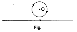
A coil of Copper wire and another wire are placed in a given figure. If the current in wire is increased from 1 A to 2 A, then the direction of current will be :
(a) Towards right
(b) Towards left
(c) Current is not induced
(d) None of these
Answer:
(a) Towards right
If the current flowing in the wire will increase from 1 amp to 2 amp then the flux linked with the coil is increase. So the direction of induced current oppose the increasing flux, according to Lenz law. So the direction of induced current is clockwise.
Question 9.
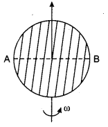
A metallic disc is moved along its axis. If uniform magnetic field is along the rotational axis, then potential difference between the diameter AB is :
(a) Zero
(b) Half of the potential difference between centre and the end
(c) Double the potential difference between centre and the end
(d) None of the above
Answer:
(c) Double the potential difference between centre and the end
The potential difference between the centre and circumference ⇒ BAf = \(\frac{1}{2}\) Br2ω
The potential difference between the ends of a diameter (AB) = BAf – (-BAf)
= 2BAf = 2 × \(\frac{1}{2}\) Br2ω
Question 10.
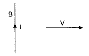
A conducting wire move towards right in a magnetic field B. Then from the given figure, the direction of induced current is given. Then, what is the direction of magnetic field?
(a) Towards left in the plane of paper
(b) Towards right in the plane of paper
(c) Normally perpendicular downwards in the plane of paper
(d) Normally upwards in the plane of paper
Answer:
(c) Normally perpendicular downwards in the plane of paper
By Fleming’s right hand rule, it is normally perpendicular and downwards to the plane of paper.
Question 11.
In an electric communication line, the current flows upwards. Considering the Earth’s magnetic field to be negligible, the direction of magnetic field on this electric line is :
(a) Towards East
(b) Towards West
(c) Towards North
(d) Towards South
Answer:
(a) Towards East
According to the right hand thumb rule, the magnetic field will in the east direction.
Question 12.
The phase difference between induced emf and magnetic flux linked with a coil rotating in a uniform magnetic field is :
![]()
Answer:
(b)
The angle between them is 90°.
Question 13.
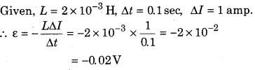
If in a coil with 2 × 10⁻³ H coefficient of self-inductance, current flows for 0.1 s is increased at a constant rate by 1 A, then the magnitude of induced emf is :
(a) 2 V
(b) 0.2 V
(c) 0.02 V
(d) Zero
Answer:
(c) 0.02 V
Question 14.
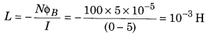
What would be the coefficient of self-inductance of a coil of 100 turns, if 5 A current flows through it? The magnetic flux is of 5 × 10³ Maxwell.
(a) 0.5 × 10⁻³ H
(b) 2 × 10⁻³ H
(c) Zero
(d) 10-3 H
Answer:
(d) 10-3 H
Given, N = 100, I = 5 amp, ϕB = 5 × 10³ Mx
= 5 × 103 × 10-8 wb
coefficient of self induction
Question 15.
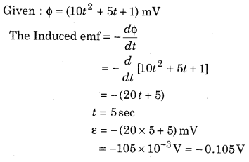
Magnetic flux passing normally through a coil, ϕ = 10t2 + 5t + 1 changes with time t is in s, ϕ m Wb-m. What is the induced emf in coil at t = 5 s?
(a) 1 V
(b) -0.105 V
(c) 2 V
(d) 0 V
Answer:
(b) -0.105 V
RBSE Class 12 Physics Chapter 9 Very Short Answer Type Questions
Question 1.
How much times would the stored energy become when current in an inductor is doubled?
Answer:
By the relation W = \(\frac{1}{2}\) LI2, 4 times.
Question 2.
Why is spark produced when we break an electric circuit?
Answer.
Due to large amount of induced e.m.f.
Question 3.
How can we increase the coefficient of mutual inductance between two coils?
Answer:
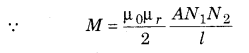
By the relation M = \(\frac{\mu_{0} N_{1} N_{2} A}{l}\)
Question 4.
What is the value of self inductance, keeping the number of turns in the coil same and doubling the cross-sectional area?
Answer:
Coefficient of self induction of coil is given by the relation : L = \(\frac{N^{2} \mu_{0} A}{l}\)
∴ L ∝ A so the self induction is 2 times.
Question 5.
How can be reduced the effect of eddy currents in a galvanometer?
Answer:
The effect of eddy currents is reduced by using soft iron core.
Question 6.
A metal and a non-metal coin were dropped from same height near the Earth’s surface. Which one of them would fall earlier and why?
Answer:
Due to the effect of eddy currents in conductor; non metal coil will reach on the surface of Earth before the metal coin.
Question 7.
Self inductance is called the inertia of electricity. Why?
Answer:
Due to the opposing nature of growth or decay of current in the coil.
Question 8.
On what factor does the coefficient of self inductance depend?
Answer:
Coefficient of self induction is given by the relation :
L = \(\frac{\mu_{0} N^{2} A}{l}\)
Question 9.
When current flows through a high voltage cable, a bird sitting on the cable flies. Why?
Answer:
Due to the effect of induced current.
Question 10.
Write the dimensional formula of \(\frac{L}{R}\), where L is self inductance and R is resistance.
Answer:
\(\frac{L}{R}\) = Time constant. [M0L0T1A0].
Question 11.
A rectangular loop is placed in a uniform magnetic field and is moved with uniform velocity. What is the value of induced emf?
Answer:
Zero, due to the no change in magnetic flux.
Question 12.
How would we wrap two coils so that maximum value of induced emf is obtained?
Answer:
The magnetic field produced in coil is in same direction.
Question 13.
On what factors do induced emf of a rotating coil (rectangular loop) in a magnetic field depend?
Answer:
The induced e.m.f. is given by coil :
ε = ε0 sinωt = NABω sinωt
Where — N = Number of turn, A = Area of cross section, B = Magnetic field, ω = Angular velocity.
Question 14.
Emf is induced when a straight long conducting wire is placed in North-South direction and is allowed to fall freely. Why?
Answer:
No, there is no change in magnetic flux.
Question 15.
How are the eddy currents used for damped oscillation in moving coil galvanometer?
Answer:
Eddy currents are produced in soft Iron core which oppose the motion of pointer.
RBSE Class 12 Physics Chapter 9 Short Answer Type Questions
Question 1.
What do you understand by electromagnetic induction? Write the laws of Faraday related with the electromagnetic induction and write the value of induced emf.
Answer:
Michael Faraday and Joseph Henry performed experiments independently and explained that the electric field produced (induced) from time varying magnetic field can produce electric current in closed coil. This phenomenon is called electromagnetic induction.
After the experiments of Henry various applications of electromagnetic induction are known. For example, the generators used at our work places to provide electric supply are based on electromagnetic induction. Electric guitars also work with the use of this phenomenon. This phenomenon is also used to melt metals fastly and safely. These days induction cookers are also popular and are replacing the traditional gas stoves. In this chapter, we will learn about the principles related to electromagnetic induction.
Faraday’s Laws of Electromagnetic Induction
On the basis of Faraday’s experiments on electromagnetic induction, he gave two laws which are called Faraday’s laws electromagnetic induction.
First Law : Whenever the amount of magnetic flux linked with a closed circuit changes, an emf is induced in it which lasts only so long as the change in flux is taking place.
Lines of field increase — Inverse current
Lines of field decrease — Direct current
Second Law : According to this law, “the magnitude of induced emf is equal to the rate of change of magnetic flux.” If the induced emf is represented by ε, then mathematically,
ε = \(\frac{d \phi_{B}}{d t}\) …………… (1)
If N is the number of turns in coil and the turns in coil are nearby, then, the flux related to each turn uniformly changes. Thus, total induced emf,
ε = \(\frac{N d \phi_{B}}{d t}\) …………… (2)
Substituting ϕB = BA cos θ
The flux in a coil can be changed by :
(i) Changing the magnetic field B in coil,
(ii) Changing the total area of coil or that area of the coil which is in magnetic field.
For example, expanding or contracting the coil for pushing it in or drawing it out.
(iii) Changing the angle between the magnetic field B and the normal of the plane of coil (or in the plane of coil). For example, rotating the coil so that initially, B is normal to the surface and then, it is along the plane.
Question 2.
A coil in a magnetic field is removed with :
(i) fast speed,
(ii) slow speed.
In which case, is the induced emf and work done more?
Answer:
By the relation : The induced emf ε = \(-\frac{d \phi}{d t}\), for fast speed dt is minimum so the induced dt emf is more.
Question 3.
Explain the Lenz’s law related to electromagnetic induction. How does Lenz’s law follow the law of conservation of energy?
Answer:
Lenz’s Law
The magnitude of induced emf is determined by Faraday’s laws but the direction of induced emf or induced current is determined by Lenz’s law.
According to Lenz’s law, “the direction of induced emf or induced current is such that it to opposes the cause which produces it.”
Taking into account Lenz’s rule for the direction of induced emf, Faraday’s law takes the form
ε = \(\frac{-d \phi_{B}}{d t}\) ……………… (1)
and for N turns in the coil, d$B
ε = \(-N \frac{d \phi_{B}}{d t}\) …………….. (2)
i. e., if the flux through a coil increases, then the induced emf tries to decrease it. Induced emf tends to oppose any magnetic change which takes place in the circuit.
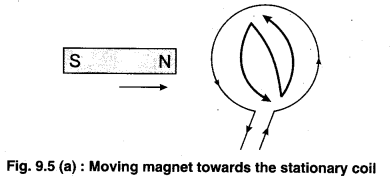
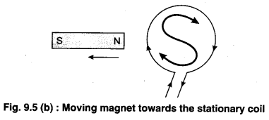
In fig. 9.5 the North pole of a bar magnet is moved’towards the coil then the direction of induced emf will be so that the coil repels the magnet, i.e., North polarity is developed on the coil.
Now, if the South pole of the magnet is moved towards the coil, upper face of coil acquires South polarity and hence opposes the motion of the magnet.
Thus, from Faraday’s and Lenz’s law,
ε = \(\frac{-d \phi_{B}}{d t}\)
Here, negative sign shows the direction of induced emf.
Lenz’s Law and Conservation of Energy
Lenz’s law is based on the law of conservation of energy. To understand it, we consider the situation in fig. 9.5. (a). Let us imagine that on bringing the North pole towards the coil, the current is so induced that the coil acquires south polarity rather than north polarity, ‘then now the magnet and the coil will not repel but attract each other. Now, on increasing the acceleration of the magnet, the current in coil would increase and hence force on magnet and hence current in coil further increases. Due to this, the kinetic energy of magnet and rate of heat in coil i2 R would increase. However, this is not in accordance with the law of conservation of energy.
From the experiments of electromagnetic induction, we have seen that in each case, to move the magnet we have to do external work against the induced emf. This mechanical work appears in the form of electric energy. Thus, total energy of the system in conserved. The mechanical work done by the external source is equal to the energy consumed in the joule heat circuit, i.e.,Lenz’s law is in accordance with the law of conservation of energy.
Question 4.
Why does an opposing force experienced while pulling or pushing a metallic plate in a uniform magnetic field?
Answer:
Due to the change in magnetic flux, the eddy currents are produced in a metallic wire. So an opposing force is experienced while pulling or pushing a metallic plate in a uniform magnetic field.
Question 5.
Gives reasons :
(i) The wires in the coil of resistance box are turned twice.
(ii) In Wheatstone bridge, initially a cell key and later galvanometer is pressed.
Answer:
(i) Each coil of resistance box is doubled back on itself while being coiled up. This is done to decrease the self induction. The current in every part of coil is equal and opposite to that of the opposite part of the coil. So the magnetic field around one part is cancelled by the magnetic field around the opposite part, thus; self induction becomes minimum.
(ii) In Wheatstone bridge, initially a cell key and later on galvanometer key is pressed. If the galvanometer’s key is pressed first then the induced current flow in the coil reduce the main current. So the error is occured in the measurement.
Question 6.
Write Fleming’s right hand rule for determining the direction of induced current.
Answer:
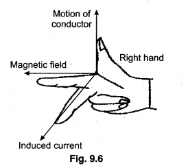
Fleming’s Right Hand Rule
The direction of induced electric current in electromagnetic induction can be determined from Fleming’s right hand rule. According to this rule, stretch the forefinger, central finger and the thumb as shown in figure (9.6), so that all three of them are mutually perpendicular to each other. If the forefinger points in the direction of magnetic field, thumb in the direction of motion of the conductor, then the central finger points in the direction of induced current in the conductor.
Question 7.
Define the coefficient of mutual inductance. Give its unit and dimensional formula.
Answer:
Coefficient of Mutual Inductance
If orientation, size and shape of primary coil C1 and secondary coil C2, remains same and in coil C1 current is I1, then second coil C2 is related to magnetic-flux which is proportional to the flow of current I2. i.e.,
ϕ2 ∝ I1
or ϕ2 = MI1 ………… (1)
Here, M is proportionality constant, which is called mutual induction. Its value depend upon number of turns, area of secondary coil and medium.
If the current in coil C1 changes with time, then flux linked with C2, i.e.,ϕ2 changes. Thus, induced emf in coil C2,
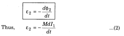
The negative sign in equation (2), indicate that the direction of induced emf in secondary coil opposes the growth or decay of current flow in a primary coil, from equation (1),
ϕ2 = MI1
If I1 = 1 Amp
then M = ϕ2 ………………… (2)
Thus the coefficient of mutual inductance is equal to the magnetic flux linked with secondary coil when the current flow in a primary coil is unity, from equation (2),
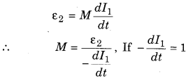
then M = ε2
Hence the coefficient of mutual inductance is equal to the induced emf when decay rate of current in primary coil is unity.
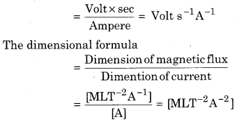
The unit of mutual inductance
M = \(\frac{\text { Weber }}{\mathrm{Amp}}\) or henry (H)
Mutual inductance depends upon the number of turns in a coil, area of cross section and medium.
The S.I. unit of M is Wb/A or VA/A or henry (H) and its dimensions are [M1L2T-2A-2].
Question 8.
A conducting wire is in North-South direction. It is freely dropped towards Earth. Is an emf induced between its ends? Why?
Answer:
No, because there is no change in magnetic flux.
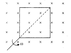
Question 9.
A conducting rod of length L is rotated in a magnetic field B with an angular velocity ω, so that the rotational plane of rod is perpendicular to the magnetic field Determine the induced emf between the ends of the rod.
Answer:
Induced emf in a Metal Rod Rotating in a Uniform Magnetic Field
In figure 9.10, a uniform magnetic field is shown by cross (×) whose direction is normally inwards the surface. A conducting rod OA of length L rotates in the anticlockwise direction in magnetic field B with angular velocity ω. The plane of rotation of rod is perpendicular to the magnetic field. When an element dl of rod moves with velocity v normally with the magnetic field, the induced emf of the element
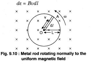
If the distance between small element and centre is l, then
v = ωl
Thus, dε = Bωldl
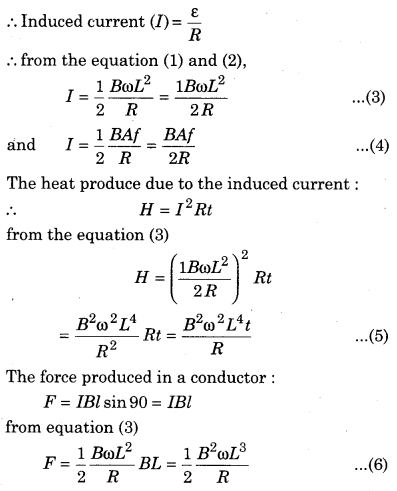
Thus, to determine induced emf in the rod, we integrate the above equation from zero to L,
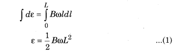
Using Fleming’s right hand rule, the direction of induced current in rod is from A to O. Thus, the end O of the rod is positive and A is negative.
If the frequency of rotation of rod is f, then to
ω = 2πf
Thus, ε = \(\frac{1}{2}\)B × 2πf × L2
= B × πL2 × f
If the area covered by the rod in magnetic field is represented by A then
πL2 = A
then ε = BAf …………………. (2)
Let the resistance of rod ‘R’ then
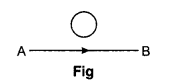
Question 10.
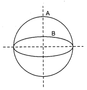
Two coils A and B are perpendicular to each other (in a given figure). There is change in current in one coil. Is current induced in the second coil? Why?
Answer:
No, because there is no change in magnetic flux in the rotation of coil.
Question 11.
On what factors do the mutual inductance depend between two coils?
Answer:
Effect of Various Factors on Mutual Inductance
The mutual inductance between two coils depend on various factors :
(i) Effect of material of core :
Clearly, M ∝ µr
“The induction between the coils become µr times on keeping a core of more relative permeability.”
(ii) Effect of number of turns : From the above formula, it is clear that .
M ∝ N1N2
If the number of turns N1 and N2 are increased, then the value of M increases correspondingly.
(iii) Effect of separation : The flux linkages decreases on increasing the separation between the coil, which decreases the mutual inductance.
(iv) Effect of coupling : If the self inductances of two coils are L1 and L2, then their mutual inductance,
M = \(K \sqrt{L_{1} L_{2}}\)
Where K is coupling coefficient.
If the magnetic flux enclosed by primary coil is also bound by secondary, then the coupling is said to 100%. In this case, K = 1,
M = \(\sqrt{L_{1} L_{2}}\)
K for different conditions
Question 12.
The self inductance of a coil is 1 H. What do you understand?
Answer:
Self inductance of coil L = 1 H
We know that
Induced emf (ε) = \(-L \frac{d I}{d t}\) ∴ ε = \(-\frac{d I}{d t}\)
Hence, when the coefficient of self inductance of coil is unity then the decay rate of current is equal to the induced emf in coil.
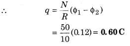
Question 13.
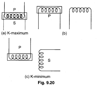
Prove that : When magnetic flux linked with a coil changes from ϕ1 to ϕ2, then induced charge, q = \(\frac{N}{R}\left(\phi_{1}-\phi_{2}\right)\), where N is the number of turns in the coil and R is the resistance of coil.
Answer:
From Faraday’s Law
Induced emf in a coil of N turns,
ε = \(-N \frac{d \phi_{B}}{d t}\)
If the area of coil is A, along the direction of magnetic field B, then magnetic flux,
From the above expressions, it is clear that the induced charge depends on the value of change in magnetic flux and not on the rate of change of magnetic flux.
Question 14.
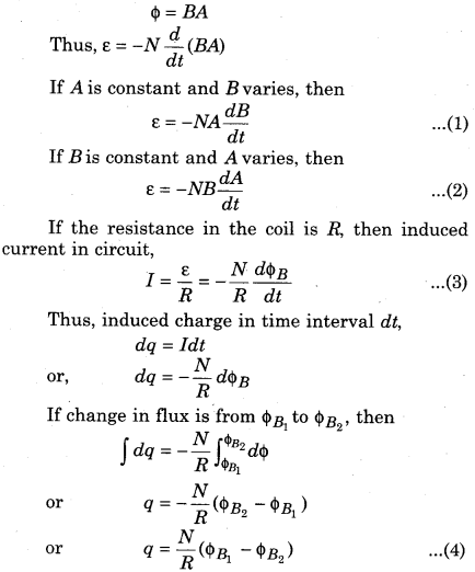
Prove that : Law of conservation of energy is obeyed when a rectangular coil is placed perpendicular in non-uniform magnetic field when it moves with constant velocity.
Answer:
Energy Conservation
According to the study in section 9.5, we can say that due to the motion of wire ab in magnetic field, positive charge is gathered at end a and negative at end b. Similarly, for wire cd, end d becomes positively charged and end c has negative charges.
If B1 > B2, then positive charge will be more on a than d. Thus, the direction of induced current in rectangular loop in adcba. Let the current be I. Force on wire ab of length l due to force on current carrying conductor in magnetic field,
F1 = IlB1 (towards left)
Similarly, force on side cd,
F3 = IlB2 (towards right)
Resultant force,
F = F1 – F3
= IlB1 – IlB2 (towards left)
The force acting on the sides bc and ad of rectangular loop, F4 and F2 are equal and opposite and hence cancel each other.
When loop move in anticlockwise direction in time Δt and travels a distance vΔt, then work done against resultant force F,
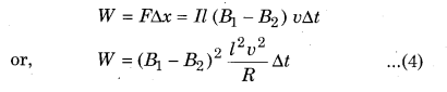
This work is present in the form of electric energy consumed in energy circuit. Thus, energy stored in the form of heat in Δt time,
H = I2RΔt
Substituting the value of I in equation (3)
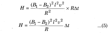
Thus, from equations (4) and (5),
W = H
i.e., Electric energy is produced by the mechanical work in electromagnetic induction. Some part of this energy is transformed into heat energy by the flow of current. Thus, energy is conserved in electromagnetic induction.
RBSE Class 12 Physics Chapter 9 Long Answer Type Questions
Question 1.
Determine induced emf due to a moving conducting rod moving with a uniform velocity in a uniform magnetic field. How is the direction of this induced emf determined?
Answer:
Induced emf in a Conducting Rod Moving in a Uniform Magnetic Field
In fig. 9.7, the uniform magnetic field \(\vec{B}\) is represented by dots. Its direction is perpendicular to the plane of paper and is directed upwards. A conducting rod ab of length l is placed perpendicular to the magnetic field. Thus conducting rod is moved with velocity \(\overrightarrow{\mathrm{v}}\) normally to both ‘ength l and magnetic field \(\vec{B}\).
The free electrons present in conducting rod also moves with velocity \(\overrightarrow{\mathrm{v}}\) in magnetic field. Thus, magnetic force acts on these electrons whose value,
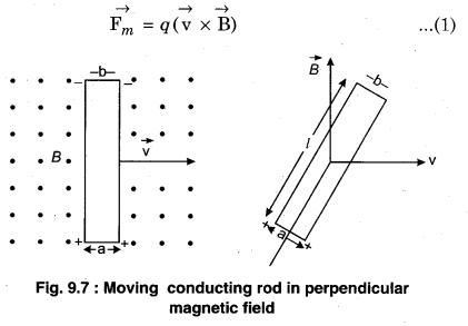
Here, q is the charge of electron. For a positive charge, the direction of \(\overrightarrow{\mathrm{v}} \times \overrightarrow{\mathrm{B}}\) is from b to a (from fig. 9.7). Thus, for negative charge of electron, the direction of magnetic force in the conductor will be from a and b. Due to drift velocity of electrons, electrons are present in large amount on end b and it is lesser at end a. Due to lesser electrons at a, the end b is negatively charged and end a has more number of positive charge.
When both the ends of different charges of the rod come close, then an electrostatic force is developed between both the ends of the conducting rod. This process continues till the force on electrons due to electric field is not balanced by the force on electrons due to magnetic field.
If the developed electric field is E, then the force that acts on the electron of charge q,
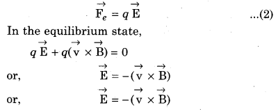
i.e., \(\overrightarrow{\mathrm{E}}\) is directed opposite to the direction of \(\overrightarrow{\mathbf{v}} \times \overrightarrow{\mathbf{B}}\) or is from end a to b in the conductor.
The magnitude of electric field, E = vB
Due to this electric field, induced emf or potential difference e is developed between the two ends of the conductor.
Thus, ε = Work done against the field in displacing the unit positive charge from one end to another = Force on unit positive charge × Displacement
ε = El
thus, ε = vBl …………. (3)
Here, l is directed from the negative terminal to the positive terminal.
Question 2.
A rectangular loop moves with constant velocity perpendicular to non-uniform magnetic field. Calculate the formula for induced emf and current for it. Prove that it obeys the law of conservation of energy.
Answer:
Induced emf and Current in a Rectangular Loop Moving in a Non-uniform Magnetic Field
In fig. 9.8, a rectangular conducting coil abed is placed normally in a non-uniform magnetic field. Let the magnetic field on side ab is B1 and that on side cd is B2. The coil is moved with velocity v normally to the magnetic field so that the direction of velocity is perpendicular to sides ab and cd.
Let the length of the sides ab and cd of the coil be l. So, the distance travelled by the coil in small time Δt is vΔt. The area crossed by sides ab or cd, ΔA = lvΔt.
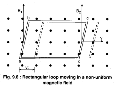
The values of magnetic fields in these elemental areas are B1 and B2 respectively. From fig. 9.8, it is clear that the area of the left coil moves out of the magnetic field B1 from the left and the same area enters, the magnetic field B2 from the right. The decrease in flux crossing the coil from left,
ϕB1 = B1 × ΔA = B1lvΔt …………. (1)
Increase in flux crossing the coil from the right,
ϕB2 = B2 × ΔA = B2lvΔt ………………… (2)
Thus, total change in the flux crossing the coil,
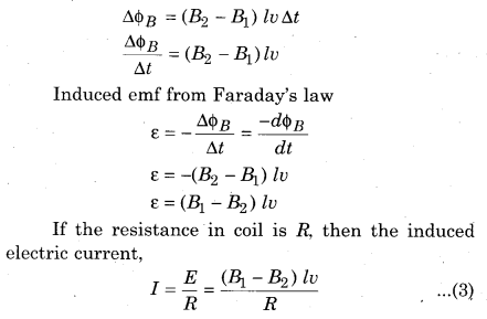
Question 3.
A rectangular coil of turns N and area A rotates with a uniform velocity to in a uniform magnetic field. Prove that induced emf in the coil is NBAω sin ωt.
Answer:
Induced emf by Changing the Relative Orientation of the Coil and the Field
In fig. 9.12(a), a rectangular coil abed is placed in a uniform magnetic field with its plane perpendicular to the magnetic field. On rotating the coil with angular velocity co, we find that the angle between the plane of the coil and the magnetic field varies continuously. Hence, magnetic flux varies. Due to this, emf is induced in the coil.
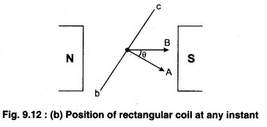
Let at time t [see fig. 9.12(a)] if the area A makes an angle θ with the magnetic field B and number of turns in the coil is N, then magnetic flux crossing the coil,
ϕB = N (\(\overrightarrow{\mathrm{B}} \cdot \overrightarrow{\mathrm{A}}\)) = NBAcosθ
ϕB = NBAcosωt …………… (1)
As the value of flux changes with time t. Thus, emf induced (from Faraday’s law)
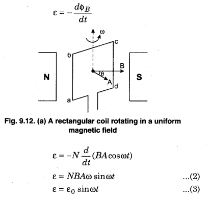
Here, ε0 is maximum value of induced emf.
ε0 = NBAω ………….. (4)
If a graph is plotted between induced emf ε and time t, then we get fig. 9.13.
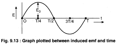
From equations (2) and (3), it can be seen that when the flux is maximum in coil, then induced emf is zero (minimum), and when flux is minimum, the induced emf is shown in fig. 9.13. If e and t is obtained as the flow current in the circuit,
I = \(\frac{\varepsilon}{R}=\frac{\varepsilon_{0}}{R} \sin \omega t\)
or, I = I0 sinωt ………… (5)
The emf represented in eqn. (2) and (5) is called alternating emf and the current is called alternating current (A.C.). This is the principle of A.C. generator.
Question 4.
What is self induction? Explain the experiments of self induction and calculate self inductance for a solenoid.
Answer:
Self Induction
When current in a coil changes, the magnetic flux linked with the coil also changes and hence emf is induced in the coil. This phenomenon is known as self induction.
According to Lenz’s law the induced emf opposes the change in magnetic flux.
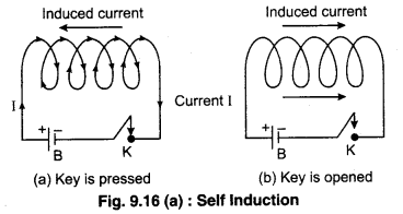
Experimental Representaion :In figure 9.16, a conducting coil C is connected with a battery and key in series. When current is passed through the key, hence magnetic flux is linked with the coil changes. When key is pressed, on increasing current, the change in magnetic flux also increase which produces emf and the induced current opposes the current that flows through the circuit. Similarly, when key is opened, the current in the circuit is zero. Then, magnetic flux linked with the coil decreases and hence the induced current flows in the direction of the current supplied. This is shown in figure 9.16 (a).
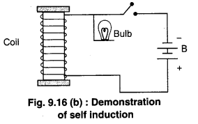
Experiment to demonstrate self induction :
Take a solenoid having a large number of insulated wire wound over a soft iron core. Such a solenoid is called a choke coil. Connect the solenoid in series with a battery, a rheostat and a tapping key. Connect a 6 V bulb in parallel with the solenoid. Press the tapping key and adjust the current with the help of rheostat so that the bulb just glows faintly. As the tapping key is released, the bulb glows brightly for a moment and then goes out. This is because as the circuit is broken suddenly. Vanishes is the rate of charge of magnetic flux linked with the coil is very large. Hence large self induced emf and current are produced in the coil which make the bulb glow brightly for a moment.
Question 5.
What are eddy currents? Write any two uses of them. How are eddy currents reduced in a transformer?
Answer:
Eddy Currents
We know that when the magnetic flux related to the closed electric circuit is changed, electric current is produced in it. Similarly, when there is change in magnetic flux in pieces of metals in a closed path, then induced current is produced in whole volume of the closed path. Their nature is circulating, that is why, they are called eddy currents. Their plane is perpendicular to the direction of magnetic field lines. These current resist the motion of metallic pieces or the change in magnetic flux. The discovery of these currents was done by Foucault in 1895. So, they are also called Foucault currents.
Experimental Demonstration of Eddy Currents
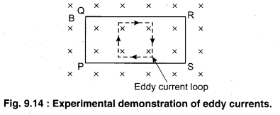
Experiment 1 : In fig. 9.14, a metallic plate PQRS is placed normally to constant magnetic field B. This plate is in plane with paper. When this plate is pulled out of magnetic field, then eddy currents are developed due to decrease in magnetic flux as the area of the plate, changes in the magnetic field. The direction of eddy currents is such that field magnetic force F = IlB opposes the motion of the plate. In fig. 9.14, the direction of eddy currents is given by Fleming’s right hand rule.
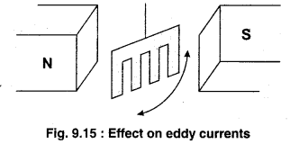
Experiment 2 : Using Aluminium sheet as a body in a magnetic field, we oscillate the Aluminium sheet. Then, the area of plate which is related to magnetic flux is not constant. The magnetic flux is minimum at extreme position of the plate and maximum at the mean position. This change in magnetic flux produces eddy current. Due to entering and leaving the magnetic field, some part of mechanical energy is transformed into heat and the plate stops moving after some oscillations. If plate is qut as shown in fig. 9.15, then it oscillates easily because, there is decrease in availability of closed paths for eddy currents and eddy currents are now weaker
Due to eddy currents in electrical appliances, most of the part of electric energy is lost in the form of heat energy. Thus, the core is laminated (split into thin sheets) to decrease the eddy currents. The core is laminated. Each lamination is insulated from other by a layer of field, we increase the resistance and hence eddy currents are reduced.
If a metal piece and a stone are dropped from same height, then, eddy currents are produced in the metal piece because of Earth’s magnetic field which tries to oppose its motion. So, the metal falls with acceleration a < g.
In a stone, no eddy currents are produced and hence its falls with a = g. So, the stone reaches the Earth eariler.
The motion of a train can be stopped by eddy currents. A metal drum is attached to the train. To apply brakes, a strong magnetic field is applied across the drum. The eddy currents are produced in the drum in the direction that opposes the change in magnetic flux, i. e., the motion of the wheel.
A coil is wrapped around the part of the patient which is to be treated and current is passed through it. This produces eddy currents in tissues and heat is produced in tissues. This is done to treat pain with heat.
Induction Furnace : In this furnace, metal is obtained from the ore. The metal to be melt is kept in alternating magnetic field, the eddy currents are produced and hence heat is produced. Thus, metal is obtained from the ore.
RBSE Class 12 Physics Chapter 9 Numerical Questions
Question 1.
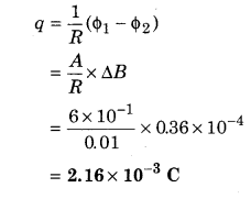
In a wall, there is a metallic framed window (120 cm × 50 cm). The total resistance of a frame is 0.01 Ω. Determine the charges flowing on opening the frame from 90°. [If H = 0.36 G]
Solution:
Given, Area of window (A) = 120 cm × 50 cm
= 6 × 103 cm2 = 6 × 10⁻¹ m2
Resistance (R) = 0.01 Ω
Magnetic field (ΔB) = 0.36 G
ΔB = B1 – B2 = 0.36G = 0.36 × 10⁻⁴ T
∴ Flowing charge in the frame :
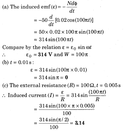
Question 2.
The magnetic flux linked with the coil of 50 turns is ϕB = 0.02 cos 100πt Wb. Determine :
(a) Maximum induced voltage.
(b) Induced emf at t = 0.01s.
(c) Induced electric current at t = 0.005 s.
(If external resistance is 100 Ω)
Solution:
Number of turns – N = 50
Magnetic flux (ϕB) = 0.02 cos(100πt) Wb
Question 3.
A coil of 50 turns is normally placed in a magnetic field of 0.6 T. The area of this coil is 0.2 m2 and the resistance in the circuit is 10Ω. Calculate induced charge when :
(a) Coil is rotated by 180°.
(b) Coil is removed from the magnetic field.
Solution:
Given, number of turns = 50, Magnetic field
(E) = 0.6T, Area (A) = 0.2 m2, Resistance (R) = 10Ω
The magnetic flux is passing through the coil in initial state (ϕ1) = BA cosθ = BA cos 0.
= BA = 0.6 × 0.2 × 1 = 0.12 Wb.
The magnetic flux, after rotating the angle of 180°
ϕ2 = BA cos(180°) = -0.6 × 0.2 ; = 0.12 Wb
∴ Induced charge
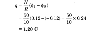
(b) The induced charge.
When the coil comes out from the magnetic field (ϕ2) = 0
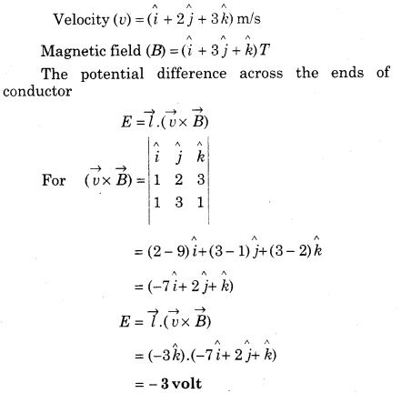
Question 4.
\(\mathbf{A}-\mathbf{3} \hat{\mathbf{k}}\) m long conductor moves with a velocity of \((\hat{i}+2 \hat{j}+3 \hat{k})\) m/s in a magnetic field of \((\hat{i}+3 \hat{j}+\hat{k})\)T. Calculate the potential difference between the ends of the conductor.
Solution:
Given, Length of conductor (l) = \(-3 \hat{k} \mathrm{m}\)
Question 5.
A rectangular coil of 1000 turns and area 0.2 × 0.1m2 rotates at 4200 revolutions per minute in a magnetic field 0.2 T. Calculate maximum value of induced emf of coil.
Solution:
Number of turns in rectangular coil : (N) = 1000
Magnetic field (B) = 0.2 T
Rotation frequency (f) = 4200 rpm
∴ Angular velocity = ω = \(\frac{2 \pi f}{t}\)
=\(\frac{2 \times \pi \times 4200}{60}\) = 439.60 rad/sec
∴ Maximum induced emf.
ε0 = NABω
= 1000 × 0.2 × 0.02 × 439.60
= 1758.4 volt
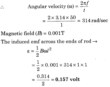
Question 6.
A conducting rod of length 1 m rotates with an angular velocity at the rate 50 revolutions per second normally to a magnetic field of 0.001 T from one end. Calculate the induced emf between the ends of the rod.
Solution:
Length of rod = 1 m
Rotational frequency (f) = 50rps
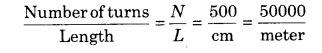
Question 7.
A solenoid of diameter 0.05 m and 500 turns/cm has length 1 m. When current of 3 A passes through it, then calculate magnetic flux.
Solution:
The diameter of solenoid (D) = 0.05 m
Radius (r) = \(\frac{0.05}{2}\) = 0.025 m
Length of solenoid L = 1 m
Current flowing (I) = 3 A
∴ The magnetic field produced by the solenoid (B) = μ0nI
= 4n × 10-7 × 50000 × 3
= 4 × 3.14 × 15 × 10-3
= 0.188 T
∴ Magnetic flux is passing through the solenoid (ϕ) = NBA = NBπr2
= 50000 × 0.188 × 3.14 × 0.025 × 0.025
= 18.49 Wb
Question 8.
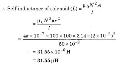
A solenoid of radius 2 cm and 100 turns has a length of 50 cm. If vacuum is inside the solenoid, then calculate the self inductance of solenoid.
Answer:
Radius of solenoid (r) = 2 cm = 2 × 10⁻² m
Number of turns (N) = 100
Length of solenoid (l) = 50cm = 50 × 10-2 m
Question 9.
Two coils are wrapped around iron core whose coefficient of mutual inductance is 0.5 H. If in 10-2 s, the value of current changes from 2 A to 3 A, then determine the induced emf in second coil.
Solution:
Coefficient of mutual inductance
(M) = 0.5 H
Time (dt) = 10-2 s, current (Ii) = 2A
Final current (If) = 3 A
Induced emf (ε) = \(-M \frac{d I}{d t}=-0.5 \times \frac{(3-2)}{10^{-2}}\)
= -0.5 × 102 = -50 volt
Question 10.
A coil is made from soft iron of length 0.1 m and radius 0.01 m. If the relative magnetisation of soft iron is 1200, then calculate the number of turns in the coil.
[Self inductance of coil is 0.25 H]
Solution:
Given, length of coil = l = 0.1 m
Radius (R) = 0.01 m
Relative permeability of free space = µr = 1200
Coefficient of self induction (L) = 0.25H
The self inductance of the coil (L) = \(\frac{\phi}{I}\)
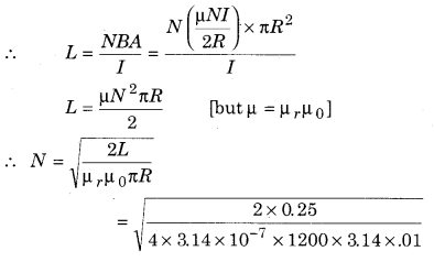
= 1.027 × 10²
N = 102 m
Question 11.
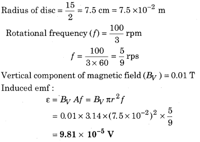
A metallic disc of diameter 15 cm rotates horizontally at \(\frac{100}{3} \) revolutions/minutes. If the value of vertical component of magnetic field is 0.01 Wb/m2. Calculate the induced emf between centre and its ends.
Solution:
Given, diameter of metallic disc = D = 15 cm,
Question 12.
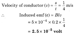
A conducting wire of length 20 cm is moving normally in a magnetic field of 5 × 10⁴ Wb/m. If the conducting wire covers 1 m distance in 4 s, then determine induced emf at the ends of the conducting wire.
Solution:
Given, Length of conductor (l) = 20cm = 0.2 m
Magnetic field (B) = 5 × 10⁻⁴ Wb/m2
Time = 4 s, Distance covered (s) = 1 meter,
Question 13.
A metallic rod of length 2 m is moved (i) vertically, (ii) horizontally with a speed of 15 km/h from West to East. If the horizontal component of Earth’s magnetic field is 0.5 × 10⁻⁵ Wb/m2 , calculate induced emf between the ends of the rod in each case.
Solution:
Given,
Length of rod = 2 m
Velocity of rod = 15 km/h = \(\frac{15 \times 5}{18}=\frac{25}{6}\) m/s W to E.
The horizontal component of Earth’s magnetic field (B) = 0.5 × 10⁻⁵ Wb/m2
(i) When the rod is moving perpendicular then BH , \(\vec{v}\) and \(\vec{l}\) are mutually perpendicular to each other.
Induced emf (e) = BHvl
= 0.5 × 10⁻⁵ × \(\frac{25}{6}\) x 2
= 4 16 × 10-5 volt
(ii) When the rod is moving horizontal then :
ε = BLv sin0
ε = 0
Question 14.
If a current of 5 A flowing in a primary coil nullifies in 2 min, then induced emf is 25 kV. Calculate the coefficient of mutual inductance.
Solution:
Given, change in current (dl) = 0 – 5 = -5A
Time (dt) = 2 ms = 2 × 10⁻³ s
Induced emf in coil = ε = 25kV = 2.5 × 10⁴ volt
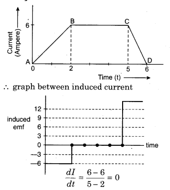
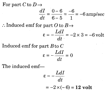
Question 15.
The inductance of a coil is 2 H. Following graph shows variation of current flowing with time t. Plot the graph for change in induced emf with time.
Solution:
For graph O to B
∴ \(\frac{d I}{d t}=\frac{6-0}{2-0}\) = 3 amp/sec
For part B to C