Exploring Some Geometric Themes Class 8 Notes
mediumExploring Some Geometric Themes Class 8 Notes
Exploring Some Geometric Themes Class 8 Notes
Fractals
Fractals are complex shapes that can be divided into smaller parts, each resembling the whole. This is called self-similarity.
Example in Nature: Fern: A fem has leaves that look like smaller versions of the whole plant.
Sierpinski Carpet
A fractal made by removing squares from a larger square.
Steps of Construction:
Step 0 : Start with 1 large square.
Step 1 : Remove the central square, leaving 8 smaller squares.
Step 2 : Repeat the process for each of the 8 remaining squares.
Patterns:
Remaining Squares : Let (Rn) be the number of remaining squares.
(R0 = 1)
(R1 = 8 × R0 = 8)
(R2 = 8 × R1 = 64)
General formula: (Rn = 8²)
Holes: Let (Hn) be the number of holes.
(H0 = 0)
(H1 = 1)
(H2 = 1 + 8 = 9)
General formula: (Hn = H{n-1} + R{n-1})
Sierpinski Triangle/Gasket
A fractal created from an equilateral triangle.
Steps of Construction:
Step 0 : Start with 1 large equilateral triangle.
Step 1 : Remove the central triangle, leaving 3 smaller triangles.
Step 2 : Repeat for each of the 3 remaining triangles.
Koch Snowflake
A fractal curve starting with an equilateral triangle. Steps to Generate:
Step 0 : Start with an equilateral triangle.
Step 1: Divide each side into 3 equal parts.
Step 2 : Construct an equilateral triangle on the middle segment and remove that segment.
Step 3 : Repeat for each straight segment.
Fractals in Art and Nature
Examples:
Kandariya Mahadev Temple : Features fractal-like structures.
Nigerian Fulani Wedding Blankets : Display fractal patterns in designs.
Coastlines: Jagged edges show fractal properties.
Clouds and Trees: Branching patterns exhibit self-similarity.
Visualising Solids
Profile : The shape visible from a specific viewpoint.
Outline: The outer boundary of the profile.
Viewpoint: The angle from which the solid is observed.
Common Solid Shapes
Cuboid : 6 faces, 12 edges, 8 vertices.
Cylinder : 3 faces, 2 edges, 0 vertices.
Cone : 2 faces, 1 edge, 1 vertex.
Prism : 2 congruent polygonal bases.
Examples : Triangular, Pentagonal, Hexagonal.
Pyramid : Polygonal base with triangular faces.
Examples : Triangular, Pentagonal, Hexagonal.
Faces, Edges, and Vertices
Faces: Flat surfaces of a solid.
Edges: Where two faces meet.
Vertices: Points where edges meet.
| Solid Shape | Faces | Edges | Vertices |
| Cuboid | 6 | 12 | 8 |
| Cylinder | 3 | 2 | 0 |
| Cone | 2 | 1 | 1 |
| Triangular Prism | 5 | 9 | 6 |
| Pentagonal Prism | 7 | 15 | 10 |
| Hexagonal Prism | 8 | 18 | 12 |
| Triangular Pyramid | 4 | 6 | 4 |
| Pentagonal Pyramid | 6 | 10 | 6 |
| Hexagonal Pyramid | 7 | 12 | 7 |
Nets of Solids
Anet is a flat representation of a solid. Examples:
Cube : 6 squares.
Cylinder : 2 circles and 1 rectangle.
Cone : 1 circle and a sector.
Tetrahedron : 4 triangles.
Projections
Showing a 3D object on a 2D plane.
Types:
Front View: Height and width.
Top View: Length and width.
Side View: Height and depth.
Isometric Projections
A way to show 3D objects where angles between axes are equal (120 degrees).
Isometric Grid : Graph paper used for drawing isometric projections.
Fractals
Definition : Fractals are complex geometric shapes that can be split into parts, each of which is a reduced-scale copy of the whole. This property is known as self-similarity.
Example in Nature : A great example of a fractal in nature is a fern.
Sierpinski Carpet
Definition : The Sierpinski Carpet is a well- known fractal created by repeatedly removing squares from a larger square. The process begins with a square divided into 9 equal smaller squares (like a tic-tac-toe grid), and the central square is removed. This process is then repeated for each of the remaining 8 squares.
Steps of Construction:
Step 0 : Start with 1 large square.
Step 1 : Remove the central square, leaving 8 squares.
Step 2 : For each of the 8 remaining squares, repeat the process of removing the central square.
Patterns in Holes and Squares
Observation : As we progress through the steps of creating the Sierpinski Carpet, we can observe a pattern in the number of remaining squares and the holes created.
- Let Rn represent the number of remaining squares at step n.
- Let Hn represent the number of holes at step n.
Finding the number of remaining squares:
At each step, every square that remains creates 8 new squares in the next step. Therefore, the relationship can be expressed as Rn+1 = 8Rn
Starting from (R0 = 1):
(R1 = 8 × 1 = 8)
(R2n = 8 × 8 = 8² = 64)
Thus, in general, we have : Rn = 8n
Finding the Number of Holes :
Each square that remains at step n creates a new hole in the next step. The holes from the previous step also remain. This gives us the relationship : Hn+1 = Hn + Rn
Starting from (H0 = 0):
(H1 = 1)
(H2 = 1 + 8 = 9)
(H3 = 1 + 8 + 64 = 73)
Sierpinski Triangle/Gasket: The Sierpinski Triangle, also known as the Sierpinski Gasket, is another fractal created from an equilateral triangle. The process involves dividing the triangle into four smaller equilateral triangles by connecting the midpoints of each side and then removing the central triangle.
Steps of Construction :
Step 0 : Start with 1 large equilateral triangle.
Step 1 : Remove the central triangle, leaving 3 triangles.
Step 2 : For each of the 3 remaining triangles, repeat the process of removing the central triangle.
Koch Snowflake
Definition : The Koch Snowflake is a fractal curve that starts with an equilateral triangle. The process involves modifying each side of the triangle to create a snowflake-like shape.
How to generate the Koch Snowflake :
Step 0 : Start with an equilateral triangle.
Step 1 : Divide each side of the triangle into 3 equal segments.
Step 2: Construct an equilateral triangle on the middle segment and remove the middle segment of the original triangle.
Step 3 : Repeat the process for each straight line segment of the resulting shape.
As you continue this process, the perimeter of the Koch Snowflake increases, and the shape becomes more intricate.
Fractals in Art and Real-World Examples
Fractals are not only found in mathematics and nature but also in art and architecture. Many traditional artworks incorporate fractal patterns, such as :
- Kandariya Mahadev Temple : This temple in India features structures that repeat smaller versions of themselves, creating a fractal-like appearance.
- Nigerian Fulani Wedding Blankets : These blankets often display fractal patterns in their designs, showcasing the beauty of self¬similarity in textiles.
- Coastlines : The jagged edges of coastlines exhibit fractal properties, as they look similar at different scales.
- Clouds and Trees : The branching patterns of trees and the shapes of clouds also demonstrate fractal characteristics.
Visualising Solids
When we visualise solids, we often describe them using specific terms that help us understand their shapes and structures;
- Profile : The profile of a solid is the shape that is visible when looking at the solid from a particular viewpoint. It is essentially the outline of the solid as seen from that perspective.
- Outline : The outline refers to the outer boundary or the perimeter of the profile of the solid. It represents the shape you would see if you traced around the edge of the solid from a specific viewpoint.
- Viewpoint: The viewpoint is the position or angle from which you observe the solid. Different viewpoints can show different profiles and outlines of the same solid.
Solid Shapes
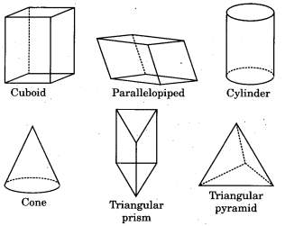
Solid shapes can be classified into various categories based on their geometry. Here are some common solid shapes :
- Cuboid : A three-dimensional shape with six rectangular faces.
- Parallelepiped : A three-dimensional shape where each face is a parallelogram.
- Cylinder : A solid with two parallel circular bases connected by a curved surface.
- Cone : A solid with a circular base that tapers smoothly to a point called the apex.
- Prism : A solid with two congruent polygonal bases connected by parallelogram faces. Examples include :
Triangular Prism : A prism with triangular bases.
Pentagonal Prism : A prism with pentagonal bases.
Hexagonal Prism : A prism with hexagonal bases.
Pyramid : A solid with a polygonal base and triangular faces that converge at a single point (the apex). Examples include:
Triangular Pyramid : A pyramid with a triangular base (also known as a tetrahedron).
Pentagonal Pyramid : A pyramid with a pentagonal base.
Hexagonal Pyramid : A pyramid with a hexagonal base.
Faces, Edges, and Vertices
In geometry, every solid shape has specific characteristics defined by its faces, edges, and vertices :
- Faces : The flat surfaces of a solid.
- Edges : The line segments where two faces meet.
- Vertices : The points where edges meet.
The number of faces, edges, and vertices for the solid shapes :
| Solid Shape | Faces | Edges | Vertices |
| Cuboid | 6 | 12 | 8 |
| Parallelepiped | 6 | 12 | 8 |
| Cylinder | 3 | 2 | 0 |
| Cone | 2 | 1 | 1 |
| Triangular Prism | 5 | 9 | 6 |
| Pentagonal Prism | 7 | 15 | 10 |
| Hexagonal Prism | 8 | 18 | 12 |
| Triangular Pyramid | 4 | 6 | 4 |
| Pentagonal Pyramid | 6 | 10 | 6 |
| Hexagonal Pyramid | 7 | 12 | 7 |
1. What is a Net?
A net is a two-dimensional representation of a three-dimensional solid. It is created by unfolding the solid along its edges, so that all the faces of the solid lie flat on a plane. Each face of the solid corresponds to a part of the net. When you fold the net back up, it forms the original solid.
2. Net of a Cube
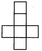
A cube is a three-dimensional shape with six equal square faces. The net of a cube consists of six squares arranged in a specific way that allows them to be folded into the cube. There are 11 different possible nets for a cube, but they all contain six squares. Here’s a simple example of one net of a cube:
3. Net of a Cuboid
A cuboid (or rectangular prism) is a three-dimensional shape with six rectangular faces. The net of a cuboid can vary depending on the dimensions of the cuboid, but it will always consist of six rectangles.
4. Tetrahedron
A tetrahedron is a three-dimensional shape with four triangular faces. It is one of the simplest three-dimensional solids. The net of a regular tetrahedron consists of four equilateral triangles arranged in a way that allows them to be folded into the tetrahedron. There are only 2 possible nets for a regular tetrahedron.

5. Net of a Cylinder
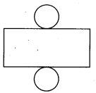
A cylinder is a three-dimensional shape with two circular bases and a curved surface connecting them. The net of a cylinder consists of two circles (the bases) and a rectangle (the curved surface). When you unroll the curved surface, it forms a rectangle whose height is the height of the cylinder and whose width is the circumference of the base circle.
6. Net of a Cone
A cone is a three-dimensional shape with a circular base and a pointed top. The net of a cone consists of one circle (the base) and a sector of a larger circle (the curved surface). When the cone is unrolled, the sector forms the curved surface, and the circle forms the base.
7. Octahedron and its Net
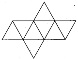
An octahedron is a three-dimensional shape made by joining two square pyramids at their bases, resulting in eight triangular faces. The net of an octahedron consists of eight equilateral triangles arranged in a way that allows them to be folded into the octahedron. Here’s a simple representation of one net of an octahedron :
8. Dodecahedron and its Nets
A dodecahedron is a three-dimensional shape with twelve pentagonal faces. It is one of the five Platonic solids. There are 43,380 different nets for a dodecahedron, which means there are many ways to arrange the twelve pentagons to create a flat representation of the solid.
9. Net of a Sphere
A sphere does not have a net in the traditional sense like polyhedra do, because it is a continuous surface without edges or vertices.
Representation of Solids on a Plane Surface
Projections : A projection is a way of showing a three-dimensional object on a two-dimensional plane. When we project an object, we imagine lines drawn from the object to the plane, and where these lines intersect the plane gives us the shape of the object as seen from a specific viewpoint.
Examples of Projections:
- Cube : When projected onto a plane, a cube can appear as a square (top view), a square (front view), and a square (side view).
- Cylinder : A cylinder can be projected to show a rectangle (side view) and two circles (top and bottom views).
- Cone : A cone can be projected to show a triangle (front view) and a circle (top view).
Planes of Projection
Vertical Plane : The vertical plane is an imaginary plane that stands upright. When we look at an object from the front, we are viewing it against this vertical plane.
Horizontal Plane : The horizontal plane is an imaginary flat surface that lies flat, like a table. When we look at an object from above, we are viewing it against this horizontal plane.
Side Plane : The side plane is another imaginary plane that stands upright but is oriented to the side of the object. This plane allows us to view the object from the side.
Views of Objects
Front View : The front view is the projection of an object as seen from the front, typically against the vertical plane. It shows the height and width of the object.
Top View : The top view is the projection of an object as seen from above, typically against the horizontal plane. It shows the length and width of the object.
Side View : The side view is the projection of an object as seen from the side, typically against the side plane. It shows the height and depth of the object.
Shadows : A shadow is a dark shape produced when an object blocks light from a light source. Shadows can give us a visual representation of the object’s shape and size, similar to projections.
For example, if you shine a light on a cube, the shadow it casts on the ground will resemble the cube’s projection.
Isometric Projections : An isometric projection is a specific type of projection where the object is tilted in such a way that the angles between the axes are equal (120 degrees). This type of projection allows us to see three sides of an object simultaneously.
Isometric Projection of the Cube : In the isometric projection of a cube, all three dimensions (length, width, and height) are represented equally. The edges of the cube appear at equal lengths, and the cube looks like a hexagon when projected.
Isometric Grid : An isometric grid is a type of graph paper that is used for drawing isometric projections. It consists of a- series of parallel lines that are spaced evenly apart, forming a pattern of equilateral triangles. This grid helps in accurately representing three-dimensional objects in two - dimensions by maintaining the correct angles and proportions.